
HC2-F versions: 13 different intensification factors
PIN: 20–207 bar
PH: 800 bar maximum
PRETURN: As low as possible (return pressure to tank)
POUTLET: PH = (PIN – PRETURN) i (intensification)
Mounting: Flange, manifold system miniBOOSTER pattern
Weight: 1.2 kg.
Model versions:
A model = no dump valve
B model = with dump valve
G model = direct proportionally controlled
Material certificate 3.1 on request
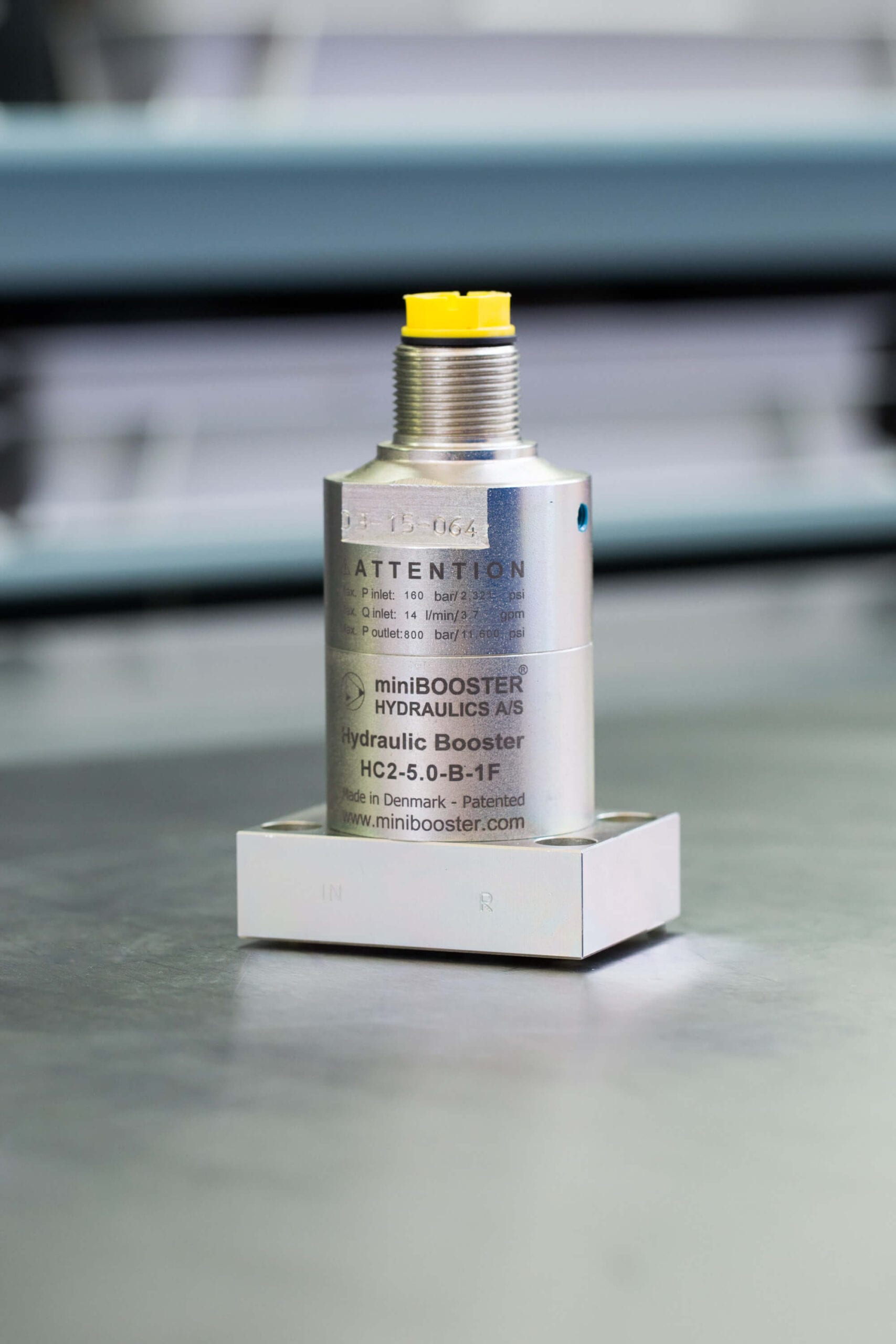
The HC2-F is a variant of the HC2 for flange mounting on the low pressure side. The entire pattern is a miniBOOSTER design. It is a compact unit weighing only 1.2 kg. It is ideal for use in a variety of applications where building and maintaining high pressure is required.
The HC2-F raises supplied pressure to a higher outlet pressure and automatically compensates for consumption of oil to maintain the high pressure. Adjustment of the outlet pressure is carried out by varying the supplied pressure.
| Intensification factor i | Max. intensified outlet flow l/min | Max. inlet flow l/min |
|---|---|---|
| 1.2 | 3.5 | 8.0 |
| 1.5 | 4.2 | 12.0 |
| 2.0 | 3.2 | 12.0 |
| 2.2 | 2.9 | 12.0 |
| 2.5 | 2.7 | 13.0 |
| 2.8 | 2.5 | 13.0 |
| 3.2 | 2.5 | 15.0 |
| 4.0 | 2.0 | 14.0 |
| 5.0 | 1.6 | 14.0 |
| 6.6 | 1.3 | 13.0 |
| 9.0 | 0.9 | 13.0 |
| 13.0 | 0.6 | 12.0 |
| 20.0 | 0.3 | 12.0 |
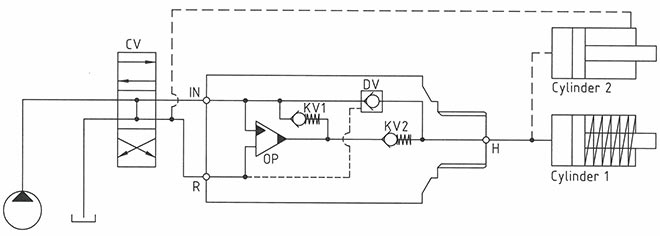
The basic operation is illustrated in the function diagram. Oil is fed through the directional valve CV to the IN port, flowing freely through the check valves KV1, KV2 and DV to the high-pressure side H. In this condition maximum flow through the booster is achieved giving a fast-forward function.
When pump pressure is reached on the high-pressure side H, valves KV1, KV2 and DV will close. The end pressure will be achieved by the oscillating pump unit OP. The unit will automatically stall when end pressure on the high-pressure side H is reached. If a pressure drop on the high-pressure side exists due to consumption or leakage, the OP valve will automatically operate to maintain the end pressure.
2-105-01
Download
Dimension drawing 2-135-01
Download
| Connection | IN / R | H |
|---|---|---|
| 1F | Flange | 1/4" BSPP |
| 2F | Flange | 9/16-18 UNF |

© 2019 南京惠言達電氣有限公司 版權所有 備案號:蘇ICP備2021018979號-1 技術支持:化工儀器網 GoogleSitemap 總訪問量:533815 管理登陸